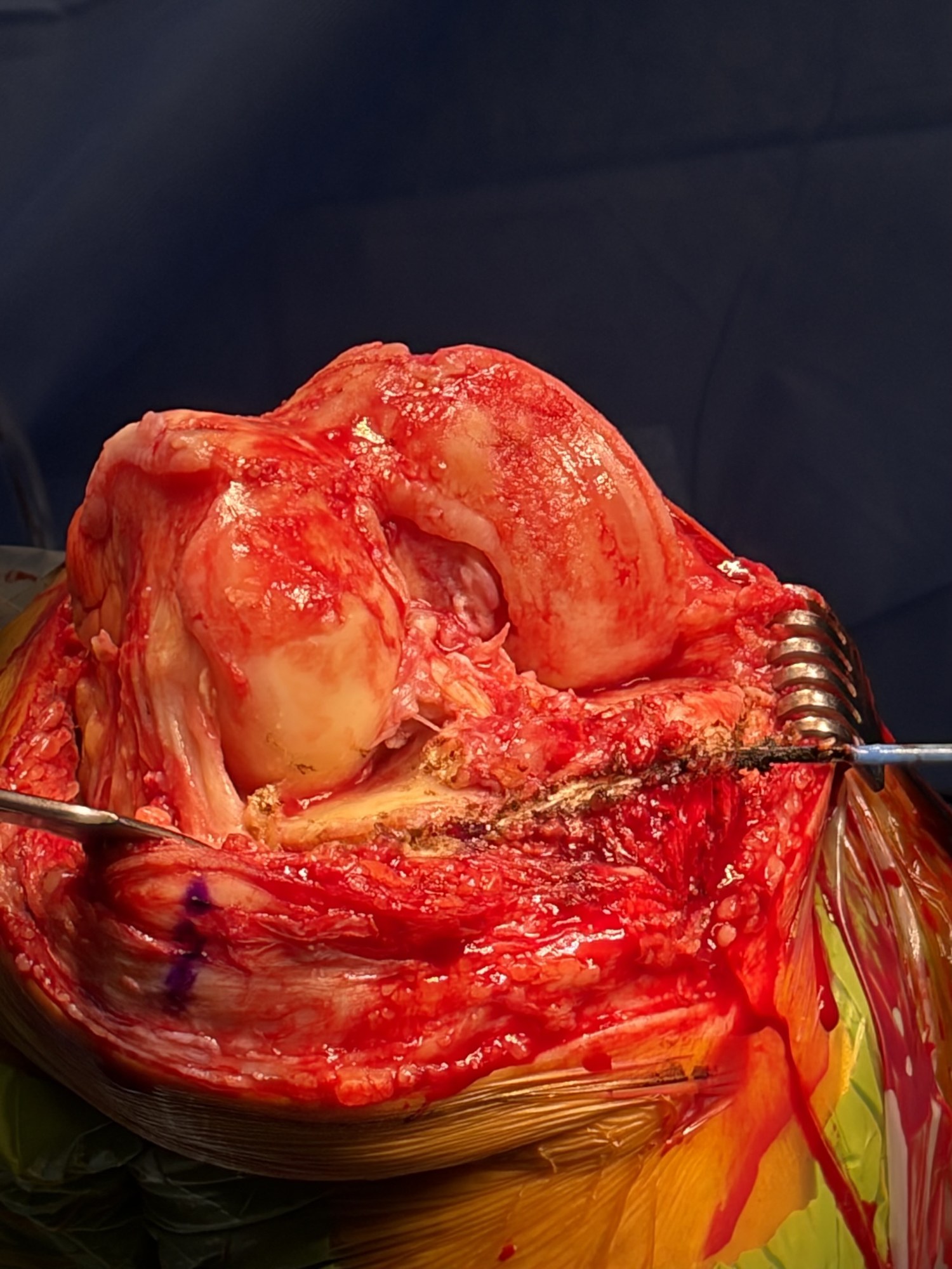
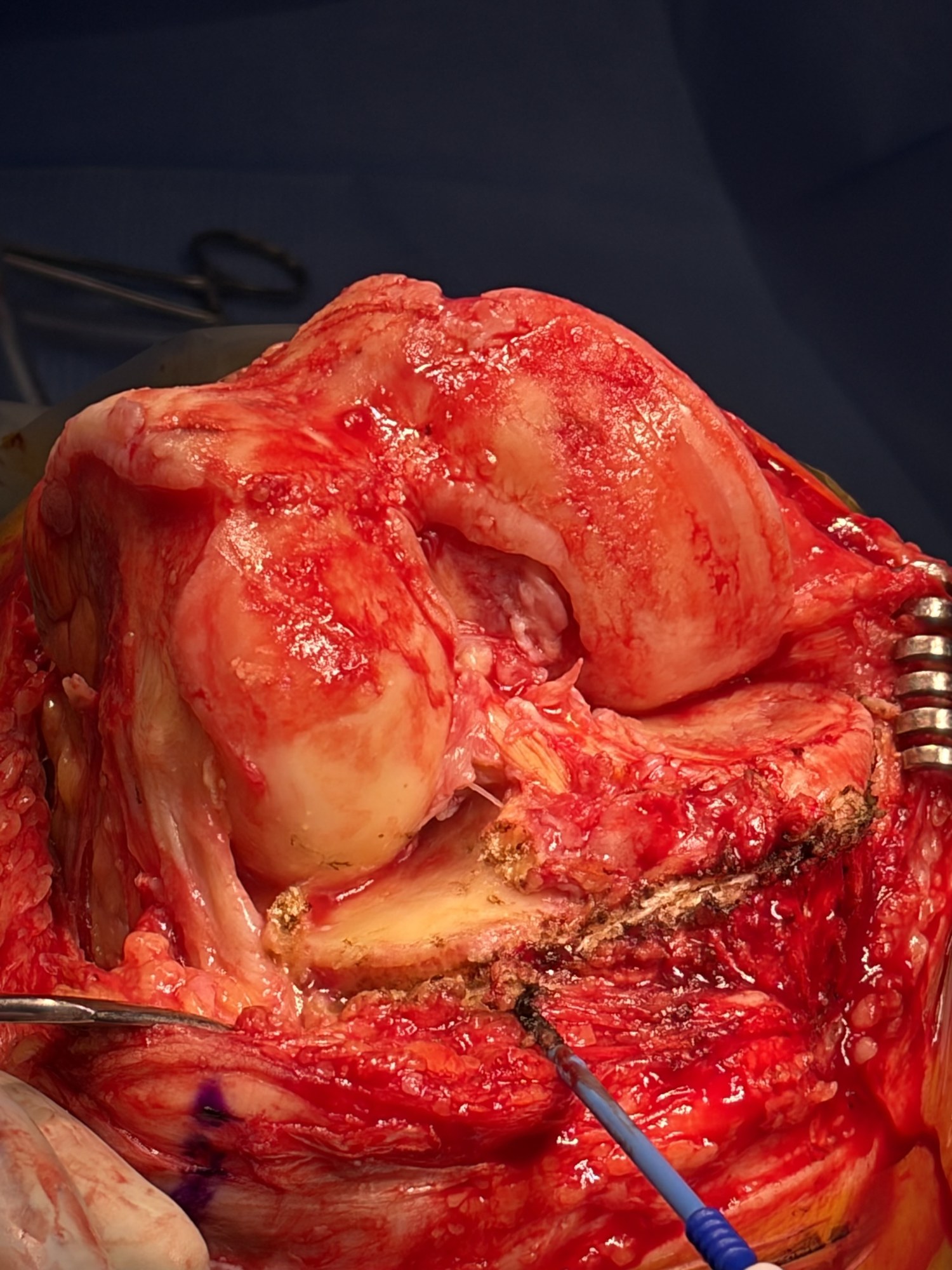
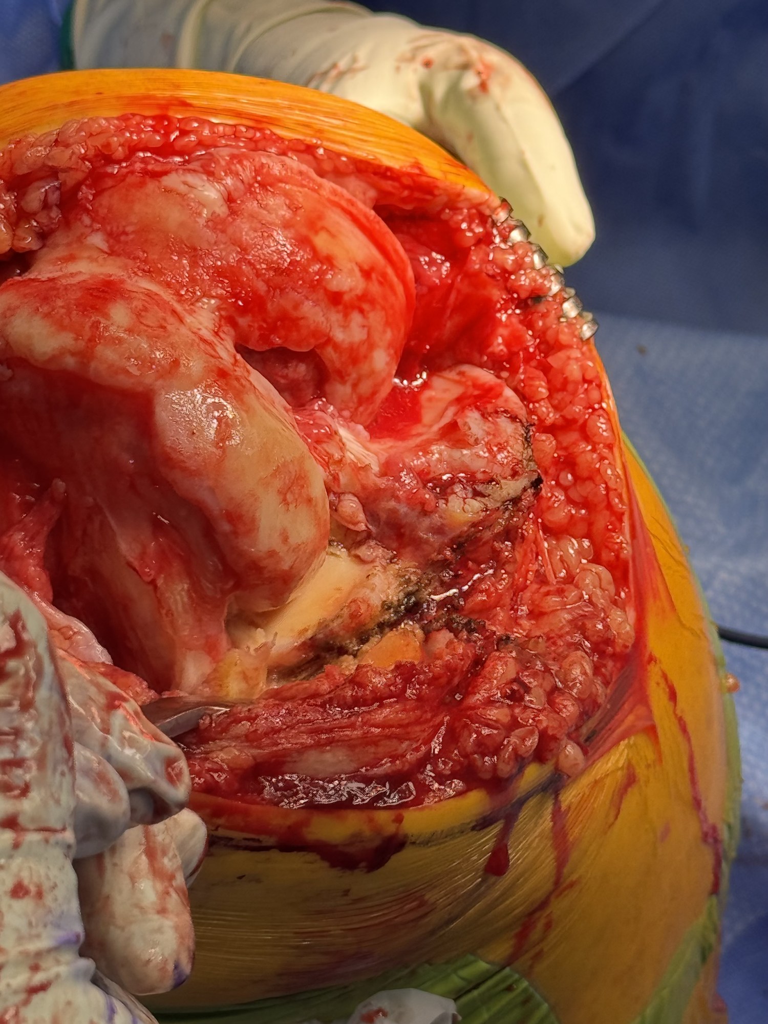
Follow the medial side: it travels less in this teaching model. Stability does not mean no movement.
Teal: medial · Amber: lateral. Select a cue to show illustrative paths from above.
Preparing the motion comparison…
Illustrative 0–120° motion, synchronized by flexion angle. Existing teaching implants; not the proposed implant design or measured postoperative motion. The animation demonstrates a restoration goal, not a predicted result.
Part 1
Anatomy & motion.
What the reconstruction restores: each surface, the joint line, the patient's alignment and how the native knee moves.
ANATOMICAL REFERENCES
Femur and tibia. Understand each surface.
Inspect condylar shape, distal joint-line orientation and the medial sagittal slope.
01 · FEMUR
Different contours. Distinct references.
Compare distal height, sagittal curvature and whole-condyle proportions. Similar posterior curvature does not make the complete medial and lateral condyles identical.
Loading femoral anatomy…
Inspect the medial and lateral condyles with intact cartilage.
Illustrative geometry. Surface traces are not fitted circles or axes of rotation. The gold distal line is a surface reference; the dashed shaft line is not a measured mechanical axis.
Femoral anatomy · findings and references
Curvature is a regional description
Elias examined 16 knees radiographically and 10 autopsy knees. The distal condyles, posterior condyles and patellar groove were described with separate circular approximations. These anatomical approximations do not establish one universal radius or validate the traces shown here.
Matsuda compared 30 normal and 30 varus knees using MRI. The distal medial condyle differed in varus knees, while the posterior medial region did not differ significantly. This supports examining distal and posterior regions separately; it is not evidence that every arthritic knee preserves the same posterior reference.
Meier’s 517-knee MRI series measured condylar lengths and anterior/posterior offsets. Mean posterior offsets were 25.7 mm medially and 23.6 mm laterally. These are distances from the posterior femoral cortex reference, not curvature radii. The cohort included 108 knees with KL 3–4 osteoarthritis; it was not a wholly healthy sample.
The existing cartilage-coated model is reused. Its shape variants are authored examples, not subjects from these studies. The femoral head is absent: neither mLDFA nor a clinical mechanical axis is established by the displayed shaft reference.
02 · TIBIA
The medial slope is our sagittal reference.
Inspect the coronal orientation and medial posterior slope. The medial plateau is the sagittal reference used in this technique; compartment differences remain in the anatomy references below.
APCoronal slope
Outer · lateralInner · medial
LateralMedial slope reference
BackFront
Loading tibia views…
Coronal orientation and medial sagittal reference.
Illustrative 2D projections. The gold sagittal guide identifies the medial reference. The lateral contour is held fixed and is not a second cutting target. The image does not measure either compartment. Positive sagittal values indicate posterior slope; negative values indicate anterior slope. Coronal zero is perpendicular to the illustrated shaft; positive places the lateral side higher. These are not MPTA readings, patient measurements, or cutting targets.
Tibial anatomy · findings and references
MRI geometry · 55 knees
Hashemi studied subjects without substantial OA or ligament, meniscal or cartilage injury. Across the male and female groups, reported ranges were coronal −1° to 6°, medial −3° to 10°, and lateral 0° to 14°. These set the explorer’s bounds; slider combinations are not study participants. Weak correlations do not establish statistical independence.
The study measured subchondral bone relative to a tibial shaft reference. It described medial concavity and a mostly flat central lateral bearing region within an overall convex lateral geometry. These are not cartilage-surface measurements.
Nunley measured the osteoarthritic compartment relative to a plane perpendicular to the sagittal tibial mechanical axis. Mean posterior slope was 6.8° in medial-UKA candidates and 8.0° in lateral-UKA candidates. These are separate groups, not paired medial and lateral measurements in every knee.
Preoperative arthritic anatomy does not establish the pre-arthritic surface. Do not pool these CT values with Hashemi’s MRI ranges or use either as a universal resection target.
Siddiqi compared 965 healthy and 193 osteoarthritic knees using CT. Femoral geometry and compartment-specific tibial slopes differed between groups. This is the study linked from the current patient tibial section; it is not the source of this explorer’s slope ranges and does not validate its animation.
Measurement axis, plane, tissue boundary and population must be specified when comparing slopes. The restored illustrations demonstrate variation; they do not calculate ligament force, contact pressure or surgical outcomes.
Explore the native surfaces and restraints
Inspect both articular surfaces, then compare the cruciates, collateral ligaments and menisci through flexion.
01 · Anatomic resurfacing
Restore the femoral surface. Restore the tibial surface.
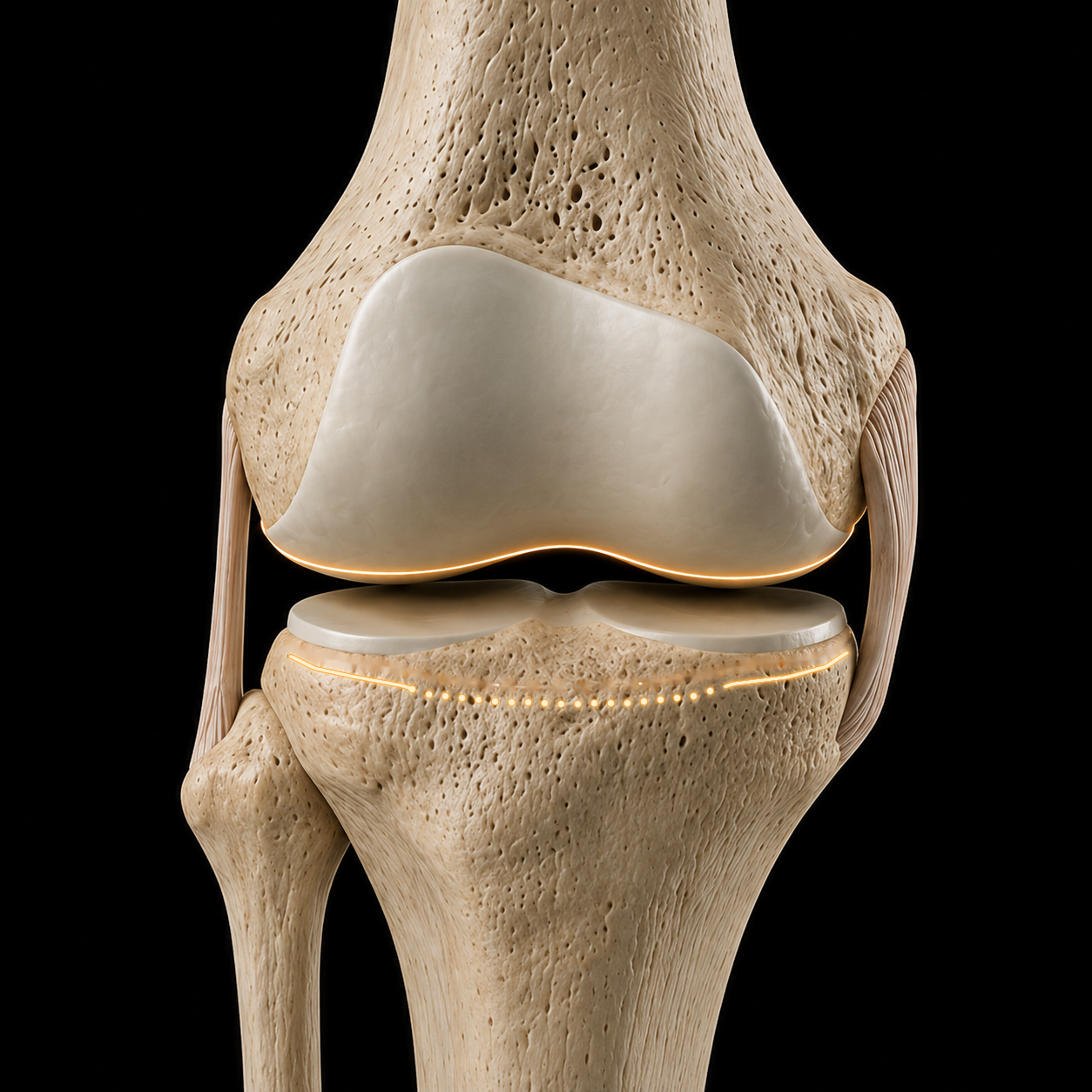
Anatomical landmarks guide reconstruction of the articular surface positions present before arthritis. Each bone provides its own reference.
Femoral referenceTibial referenceAnatomical view
Loading knee anatomy…
Cartilage-covered surfaces
Each bone has an original articular surface.
Follow the continuous cartilage over the femoral condyles and the cartilage on the tibial plateaus.
Original shells remain attached to their respective bones. Use “Expose surfaces” for a separated inspection view. This illustration does not measure contact pressure or predict knee motion.
Model and reference limits
Open Knee(s), specimen oks009. This reuses the continuous anterior cartilage surface and retained posterior bearing anatomy from the established cartilage illustration. The coating and wear are educational geometry, not a measured thickness map. Preparation and component placement are simplified. Menisci and ACL are omitted; restoration of surface position does not establish native mechanics. The tibial markers reference the model’s medial cartilage surface at one selected location; they do not prescribe a cut or validate a landmark. The insert is a simplified bearing, not manufacturer CAD. Geometry sources and license.
Femoral landmarks
Read the bone. Account for the cartilage.
Distal and posterior femoral landmarks help locate the original articular surfaces. Reconstruction must account for the cartilage that remains and the cartilage and bone that have been lost.
Tibial landmarks
Find the attachments. Recover the reference.
The deep MCL and lateral capsular attachments provide anatomical references for the tibial reconstruction. Joint-line height and coronal orientation are considered together; native slope requires a separate sagittal assessment.
Find both surface references. Reconstruct their positions. Verify how they function together.
01Find
Use femoral bone landmarks and tibial soft-tissue landmarks to estimate the native articular relationship.
02Resurface
Match the reconstruction to that reference, accounting for wear, resection, saw kerf and implant thickness.
03Verify
Measure the reconstruction and assess ligament balance, stability and motion with the trial components.
Howell’s foundation: three axes and the native joint lines
Stephen Howell, Joshua Roth and Maury Hull described kinematic alignment through the relationship between the natural joint lines and three kinematic axes: tibiofemoral flexion–extension, patellofemoral flexion–extension, and tibial internal–external rotation.
Their work explicitly describes resurfacing to restore the natural joint lines. Anatomic resurfacing places the operative emphasis on finding those references on both the femur and tibia and reconstructing the articular surfaces back to them.
Anatomical rationale supports the reconstruction goal. Restoring the joint line alone does not establish normal kinematics or superior clinical outcomes.
Explore the landmark-to-surface reconstruction example
Bone + soft tissue → joint line
AP · condyle close-up
Loading the enlarged knee…
Distal medial · 0.5 mmOther femoral cartilage · 2 mm
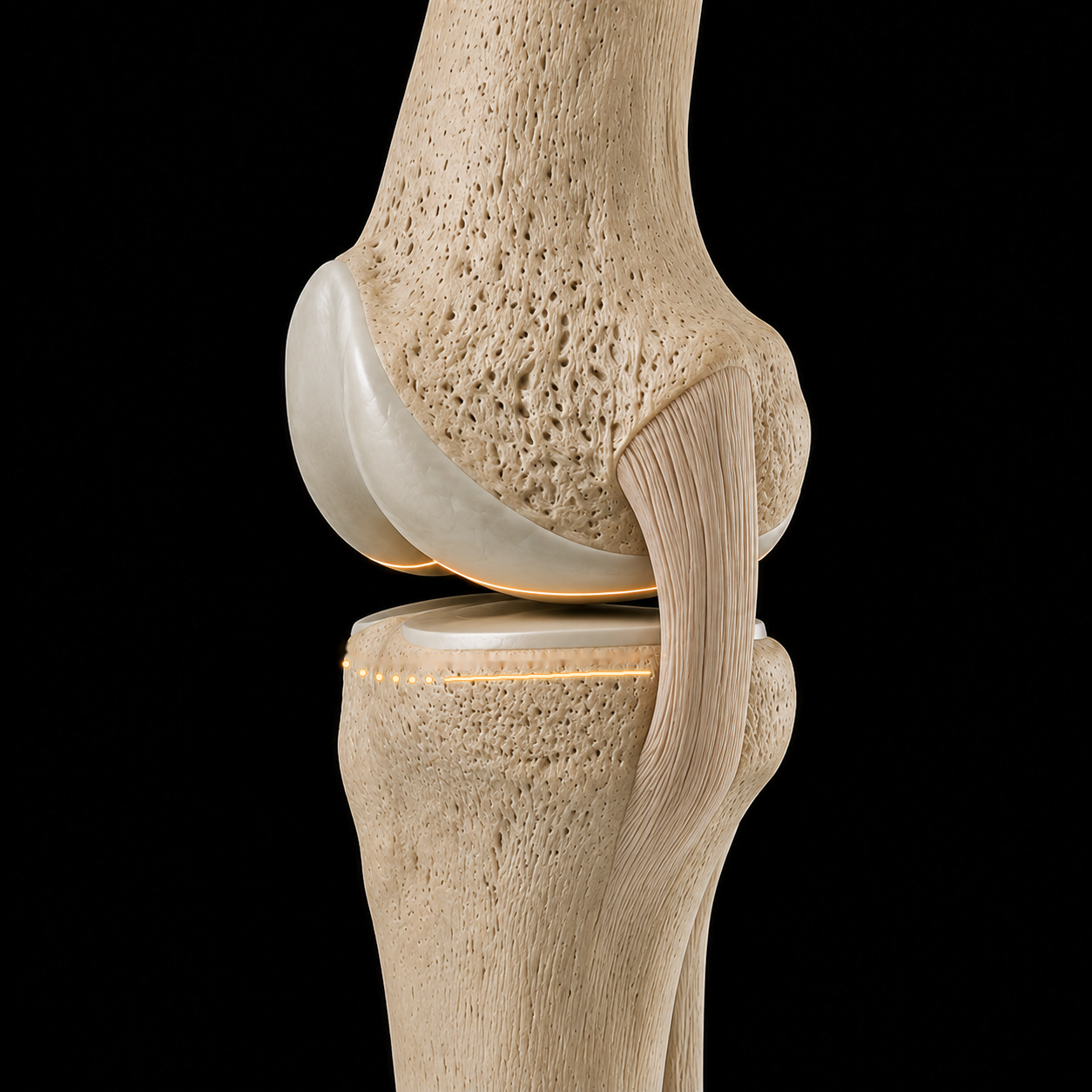
Begin with the femoral condyles and cartilage intact. The gold line marks the joint-line reference.
Cartilage is modeled at 0.5 mm distal medial, 1.5 mm posterior medial, and 2 mm elsewhere on the femur, with smooth transitions between regions. These are illustrative thicknesses. The 9 mm dimensions illustrate this reconstruction, not measurements of the source knee or a universal surgical target. The exposed femoral plane and soft-tissue attachment markers are illustrative. Confirm anatomy, implant thickness and resections in the surgical field. Existing model: Open Knee(s), oks009 ↗
The target
Resurface to the patient’s joint line.
Traditional mechanical alignment targets a neutral reconstruction. Anatomic Resurfacing targets the joint line that belonged to this knee before arthritis.
Follow one example: a native 5° varus joint line, a level mechanical-alignment reconstruction, then a resurfaced knee returned to its original angle and height.
The dotted gold line is the native reference. The solid line follows the reconstructed joint surface.
This retrospective comparison evaluated radiographic restoration. The between-group difference in joint-line obliquity change was not statistically significant (p=0.09); clinical benefit was not established.
Arthritis has worn the surfaces. The dotted gold line marks this knee’s pre-arthritic 5° varus orientation—not a target for every knee.
Illustrative AP comparison, not surgical planning. JLO means joint-line obliquity relative to the horizontal reference shown, not overall leg alignment. Elevation is shown for this example; mechanical alignment does not necessarily raise the entire joint line. The 5° target is specific to this illustration.
Joint-line restoration
The joint line shapes ligament function.
Ligaments guide the knee throughout movement. Different fibers lengthen and shorten as it bends. Restoring the native joint line aims to preserve the relationship between the joint surfaces and the ligaments.
Normal laxity varies with flexion, loading and the individual. Check the relationship throughout the bend.
Preparing the moving knee…
One ligament. Different fibers.
Each fiber follows its own path.
Anterior MCL fibersLengthen with flexion
Posterior MCL fibersShorten with flexion
Observed during walking, downhill walking and stair descent in healthy knees.
Colored paths illustrate the pattern. They are not measured strain or tension.
Illustrative anatomy and motion. No force scale, surgical target or prediction of an individual result.
Normal is asymmetric.
Healthy knees can open more laterally than medially in flexion under stress.
Normal is individual.
One person’s laxity does not define the target for another.
Geometry matters.
Joint-line height, inclination and bearing thickness are distinct changes.
What the animation shows
The normal view illustrates the direction of anterior and posterior MCL length changes reported during functional activities. These paths are not digitized study data. The LCL is on the opposite side of the knee and is not shown; its behavior varied between subjects.
The comparison is a simplified, exaggerated medial-view model: the elevated reconstruction changes the distal femoral envelope and effective hinge and adds bearing thickness. It illustrates mid-flexion slack with balanced endpoints, not the isolated effect of changing an insert. Identical native and restored motion represents the restoration goal, not a guaranteed postoperative result. Joint-line inclination is not simulated. Read the cadaver study ↗
10 healthy subjects; fluoroscopy-driven models. Anterior MCL fibers lengthened and posterior fibers shortened with flexion. Lengths were normalized to heel strike; absolute strain and ligament forces were not measured.
20 healthy knees near 90° flexion: mean lateral opening 6.7 mm under varus stress, medial opening 2.1 mm under valgus stress. Stress was not standardized and the compartments were stressed separately; these values are not TKA gap targets.
8 non-arthritic cadaveric knees. Medial contact loads exceeded lateral loads and decreased with flexion in the thigh-pull setup. Compartment contact force is not isolated collateral-ligament force or a walking load.
10 cadaveric knees, 0–120° flexion. Passive motion limits varied between knees; most comparisons between directions were not strongly correlated. Results depend on the applied loads and passive test conditions.
267 healthy knees tested with 10 Nm varus and valgus torque at 0° and 15°. Laxity varied between people and increased with flexion. This young, healthy cohort does not establish universal postoperative targets.
A cadaveric TKA reconstruction study found increased mid-flexion laxity after joint-line elevation despite maintained endpoint balance. This supports the illustrated mechanism, not a universal height-to-tension rule.
8 matched cadaver pairs. Kinematic alignment reproduced native mid-flexion MCL strain more closely than mechanical alignment in this experiment. It compared reconstruction strategies and did not isolate inclination alone or measure patient outcomes.
One knee animation. Four studies of native variation.
Loading knee anatomy…
Bellemans · group mean geometry32% male · 17.2% female
Femur · mLDFA89.0°
Tibia · MPTA85.1°
Illustrative paired knees · values drive the teaching pose, not measurements of the artwork. Both sides show the same example.
1 / 4
Constitutional varus · the study behind the animation
125 male and 125 female volunteers without orthopaedic or trauma history; both knees were assessed with 19 alignment measurements. Negative HKA denotes varus. These percentages describe knees, not people.
Varus: HKA ≤−3° · Neutral: −3° < HKA < +3° · Valgus: HKA ≥+3°. Mean HKA: −1.87° in male knees and −0.79° in female knees.
Which bone contributes?
Both distal femoral and proximal tibial geometry differed across alignment groups. MPTA had the strongest reported association with constitutional varus (R² = 0.408); mLDFA also contributed (R² = 0.294). These statistics are not additive shares of causation.
Table 2 · group means ± SD · degrees
Measurement
Varus
Neutral
Valgus
mLDFA · femur
89.03 ± 1.46
87.61 ± 1.60
85.49 ± 1.92
MPTA · tibia
85.13 ± 1.81
87.60 ± 1.74
89.06 ± 1.42
JLCA · joint-line convergence
−0.44 ± 1.11
−0.53 ± 1.04
−0.64 ± 0.85
Sport during growth: an association
No extra sport−0.9°School activity only · mean HKA
1–3 hours / week−1.3°Additional impact sport · mean HKA
>3 hours / week−2.3°Additional impact sport · mean HKA
Activity in the second decade of life was associated with greater varus. The highest-activity group differed from school-only activity (p < 0.01) and 1–3 hours/week (p < 0.05). Retrospective activity reporting and a cross-sectional design do not establish cause.
Clinical interpretation, methods & source checks
Native alignment is variable, and forcing every knee toward the same geometric pattern may change its anatomy. This study did not compare postoperative targets, implant survival or clinical outcomes. Young volunteers do not represent all arthritic knees. Radiographic positioning and a single reader are measurement limitations.
Source: Bellemans, Colyn, Vandenneucker & Victor. CORR 2012;470:45–53. DOI 10.1007/s11999-011-1936-5. Prevalence and bone angles above follow the paper’s tables. Table 1 and the results prose swap the male/female HKA standard deviations; only the consistent sex-specific means are shown here.
Illustrative anatomy and example angles, not patient measurements or surgical targets. Playback is a teaching sequence, not a population distribution.
Studies, definitions & limits
The patient-side knee artwork is reused throughout. The animation shows alignment and joint-line tilt; it is not a full-limb radiographic measurement or a biomechanical simulation. Each study keeps its own cohort and definitions. The healthy Belgian cohort in the original CPAK study draws on the constitutional-varus work; these are not independent population samples.
LDFA: lateral distal femoral angle. MPTA: medial proximal tibial angle. Original CPAK estimates constitutional alignment with their difference and describes joint-line obliquity with their sum. Functional phenotyping and modified CPAK use different group definitions. No automatic conversion between their category labels is implied.
These anatomy and classification findings do not establish a superior postoperative target or long-term clinical outcome.
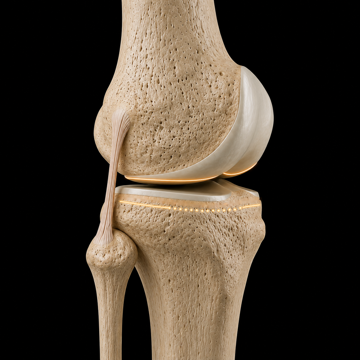
Motion emerges from the surfaces, menisci and ligaments together. The animation is an unloaded teaching reference built from cadaver MRI (Iwaki, Pinskerova and Freeman): prescribed values, not measured living-knee or implant kinematics. Load, activity and the individual knee change the pattern.
ANATOMIC RESURFACING UNLOADED TEACHING REFERENCE
Unloaded teaching reference.
Right knee · Full extension
Preparing the 3D knee…
Medial condyle Medial plateau · concaveLateral condyle Lateral plateau · flat / slightly convex Fibula marks the lateral side
FIBULA · LATERAL
FLEXION0°
MEDIAL AP · POSTERIOR0.0 mm
LATERAL AP · POSTERIOR0.0 mm
TIBIAL INTERNAL ROTATION0.0°
0.0 / 25 s
How the pattern changes
Living-knee MRI · 0–120°
Weight-bearing motion
Same knee model. Different loading conditions.
In this small MRI study, lateral rollback occurred earlier during a weight-bearing squat. Switch conditions at the same flexion angle to compare.
Follow the teal medial and amber lateral dots. Their trails show where the model’s estimated contact locations have travelled; use Axial view to compare both compartments.
Pinskerova et al. (2004), Table I · Five volunteers, both conditions. Published mean condylar-center positions drive this illustration; motion between samples is interpolated.
A study-specific squat example—not a walking pattern, a universal normal knee, or an implant-performance comparison.
Weight-bearing changes with the activity
Walking, squatting and lunging measure different parts of knee function. These studies add context; their trajectories are not blended into the animation.
Squat · WB versus NWB
Rotation starts earlier under load
In 20 male volunteers, dynamic fluoroscopy showed earlier femoral external rotation during a squat than during seated non-weight-bearing flexion.
Bone landmarks and lowest surface points were tracked; ligament forces were simulated.
In eight healthy knees, the location of peak cartilage contact deformation travelled farther front-to-back medially than laterally during treadmill stance.
MRI and dual fluoroscopy measured cartilage contact deformation, not condylar-center travel.
Eight knees in seven healthy participants showed distinct phases of rotation during a weight-bearing lunge. Contact-point movement also changed in deep flexion.
MRI and dual fluoroscopy at held positions; a lunge is a different task from walking or a bilateral squat.
In nine healthy men, MRI under 400 N axial load showed larger cartilage-to-cartilage contact areas in both compartments, with different meniscal contact responses.
Static loading in an MRI scanner, not dynamic gait. The animation does not model menisci, deformation or pressure.
The MRI table reports positions at 0°, 20°, 45°, 90° and 120°. At 45°, lateral posterior travel is 13 mm loaded versus 2 mm unloaded. Medial travel is 1 mm anterior in both conditions. At 120°, lateral travel is 20 versus 14 mm, respectively.
The original surface model, cameras and seating method are reused. AP motion follows the table; axial rotation is derived to fit this model’s reference-center spacing. Coronal seating and vertical clearance are geometric corrections, not measured weight-bearing responses. The animation does not calculate muscle forces, ligament tension, cartilage pressure or ground reaction forces. Playback timing is illustrative. The colored dots and trails are smoothed surface-proximity estimates calculated separately for each condition from this model. They are not the MRI study’s measured contact points or contact areas, and should not be interpreted as pressure maps.
Johal et al. (2005) also observed earlier and greater rotation under load. Hill et al. (2000) reported approximately 4 mm medial forward movement in a separate loaded cohort. These observations are not averaged into this trajectory.
A 2018 in-vivo fluoroscopy study found activity-dependent patterns, including bicondylar rollback during later squat flexion. Different measurements and cohorts need separate interpretation. This native-knee illustration does not establish the design rationale or performance of Persona, medial-pivot or other implants.
The published figures behind the animationUnloaded, loaded and beyond 120°: the studies and their limitsFaculty lesson: Kinematics of a Native Knee · Michael Hellman, MD, 2024Optional: contact regions, reference centers and synchronized viewsSources, measurements, and what the teaching animation represents
The live values are prescribed animation targets, not measurements from this specimen. Medial AP is the flexion-facet-center translation, not the migrating contact point. The animation uses 1 mm medial and 20 mm lateral posterior translation with 19.9° coupled rotation at 120°. The sagittal overlays identify the flexion-facet centers; they do not represent contact patches. The bone positions include a geometric surface-clearance correction, not a force-based cartilage simulation.
The medial-pivot pattern is a teaching reference, not an invariant rule or evidence favoring a particular implant design. Hill reported approximately 4 mm medial forward movement in loaded knees. Komistek studied five knees and reported individual variation, including a lateral-pivot subject. These studies do not establish that every native knee has no medial rollback or that loading affects timing alone.
[S15] Hill et al. (2000) ↗Hill PF et al. · 2000 · Living-knee MRI studyScope & limitations — loaded and unloaded living-knee MRI; similar overall pattern with load-related differences.
[S17] Freeman & Pinskerova (2005) ↗Freeman MA et al. · 2005 · Anatomy and kinematics reviewScope & limitations — 0–120° medial stability, early contact transfer and lateral rollback; deeper flexion is outside this film.
Bone geometry: Open Knee(s), specimen oks009, mirrored to a right-knee teaching reference. Articular surfaces and ghosted menisci are illustrative. Geometry, animation license and adaptation details. This is not a patient-specific or validated joint-contact simulation.
The operation in order: find the references, femur first, tibia second, put back what you take out, then verify by trialing and the patellofemoral joint.
The technique · One knee throughout
Follow the reconstruction.
Follow the references, preparation, trialing and patellofemoral evaluation.
Gold: original articular reference
Preparing the reconstruction…
Step 1 / 5
Find the references
Reference
Preserved native articular surfaces
Action
Identify preserved cartilage and account for wear before setting reconstruction targets.
Verify
Which reference is preserved, and which has been altered?
Schematic teaching sequence using the existing anatomy and implant models. Preparation masks and component seating are simplified; the sequence does not depict instrument use or prescribe an operative order. The patella is omitted from this overview and is evaluated in step 5 using the existing patellofemoral animations. Motion is illustrative, not a measured surgical result.
Find the references
Anatomic landmarks.
Femoral bone landmarks and tibial soft-tissue landmarks guide the cuts. Account for the cartilage that has worn away, then reconstruct the surfaces present before arthritis.
Trochlear cartilage · Anatomic Tibial LineDrag to change view
Cartilage
Cartilage · the missing millimetres
Account for wear. Restore the surface.
Cartilage loss changes the reference for femoral resurfacing. Distinguish remaining cartilage, estimated wear and bone loss when planning the original surface level.
Original joint line Planned surface level
Outer sideInner side
Planning lines over native anatomy. Offsets enlarged for clarity.
A teaching example
Cartilage lost 3 mmAccounted for 2.0 mm
1.0mm
Too high.
Underestimating the missing cartilage places the planned femoral surface above its original level.
1 mm2 mm3 mm · target4 mm
Where the correction is applied
A thickness error shifts the surface level.
The joint line helps determine how the surfaces and ligaments work together. Restoring it means accounting for the tissue that is missing.
Illustrative anatomy and planning arithmetic. The 3 mm example is not a measurement of this knee or a standard correction for every patient. Bone loss and other surgical factors also matter.
Cartilage thickness · evidence and planning limits +
Imaging · 25 knees
An X-ray shows the space.
Cartilage is seen directly on MRI. X-ray joint space is an indirect measurement influenced by cartilage, the menisci and positioning. Loading changes the measurements, but does not make them interchangeable.
Femoral cartilage wear followed recognizable patterns in straight and bent positions. Femoral bone wear was uncommon in this study. This does not mean every arthritic knee has no bone loss, particularly on the tibia.
Unworn femoral cartilage averaged 2.0–2.2 mm, with variation between patients and locations. Remaining cartilage provides clues to the original surface; it cannot establish the exact thickness of every worn area.
These studies help explain the anatomical goal of restoration. They do not show that cartilage measurement alone guarantees better function. Assessment also considers bone loss, alignment and the soft tissues.
Planning context: assess distal and posterior femoral wear separately. The demonstration isolates a cartilage estimate; it does not calculate bone resection, implant thickness or saw kerf, and does not model ligament balance.
Compare the distal and posterior surfaces. Account for cartilage at each reference.
Cartilage thickness enlarged 3× for visibility. Bone size is unchanged. Thin cartilage is translucent. Both views use the same femur.
Distal surfaceExtension reference
Preparing the femoral surfaces…
Medial0.05 mm
Lateral1.8 mm
Medial wear. Lateral cartilage remains.
Lateral 1.8 mm
Medial 0.05 mm
Posterior surfaceFlexion reference
Preparing the femoral surfaces…
Medial1.5 mm
Lateral1.9 mm
Posterior medial cartilage often remains.
Medial 1.5 mm
Lateral 1.9 mm
Remaining cartilageBone
Illustrative cartilage on the existing femur, not a patient measurement. Numbers are mean remaining cartilage before removal; the small profiles compare those means on one scale. Distal and posterior bone are revealed together.
Remaining cartilage · study values and limits
Nam et al., 2014 · 154 varus and 54 valgus knees with advanced (KL 3–4) osteoarthritis. Values are mean remaining femoral cartilage, in millimetres.
Reference
Varus medial
Varus lateral
Valgus medial
Valgus lateral
Distal · 0°
0.05 mm
1.8 mm
1.5 mm
0.2 mm
Posterior · 90°
1.5 mm
1.9 mm
1.9 mm
0.8 mm
Distal and posterior wear must be assessed separately. The appearance and thickness vary between knees. These data do not specify tibial cartilage thickness, ligament tension, or the clinical effect of a 1 mm difference.
Johnson/Ford (2025) also found variable preservation: the posterior medial femur was judged unworn in 45% of varus knees; the posterior lateral femur was unworn in 33% of valgus knees. “Worn” does not mean absent.
The lateral capsule above Gerdy’s tubercle and the deep MCL insertion at the mid-coronal plane of the tibia serve as references for varus/valgus orientation and tibial cut depth.
MedialDeep MCL insertion
LateralCapsule above Gerdy’s tubercle
Anatomic Tibial Line
Medial
Deep MCL insertion at the mid-coronal plane.
Lateral
Capsular attachment above Gerdy’s tubercle.
Anatomic Tibial Line
Connect the references to guide orientation and depth.
Conceptual educational render. Confirm landmarks directly in the surgical field.
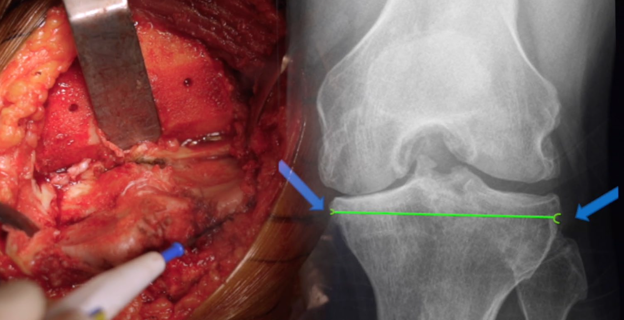
The Tibial Signature · Radiographic reference
Radiographic signature.
From the surgical field to the AP radiograph.
Archives of Orthopaedic and Trauma Surgery · Knee Arthroplasty
Specific tibial landmarks to improve to accuracy of the tibial cut during total knee arthroplasty. A case control study
Sébastien Parratte, Zakee Azmi, Jeremy Daxelet, Jean-Noël Argenson, Cécile Batailler.
A 2024 retrospective case-control study compared 34 landmark-guided TKAs with 34 matched conventional TKAs.
87.2°Postoperative MPTA landmark group47%MPTA outliers landmark group71%MPTA outliers control group
Surgical steps · 03
Femur first.
Assess. Mark. Resect.
Femoral anatomy · cartilage & bone
Distal cartilage & bone.
Compare the distal and posterior surfaces. Account for cartilage at each reference.
Cartilage thickness enlarged 3× for visibility. Bone size is unchanged. Thin cartilage is translucent. Both views use the same femur.
Distal surfaceExtension reference
Preparing the femoral surfaces…
Medial0.05 mm
Lateral1.8 mm
Medial wear. Lateral cartilage remains.
Lateral 1.8 mm
Medial 0.05 mm
Posterior surfaceFlexion reference
Preparing the femoral surfaces…
Medial1.5 mm
Lateral1.9 mm
Posterior medial cartilage often remains.
Medial 1.5 mm
Lateral 1.9 mm
Remaining cartilageBone
Illustrative cartilage on the existing femur, not a patient measurement. Numbers are mean remaining cartilage before removal; the small profiles compare those means on one scale. Distal and posterior bone are revealed together.
Remaining cartilage · study values and limits
Nam et al., 2014 · 154 varus and 54 valgus knees with advanced (KL 3–4) osteoarthritis. Values are mean remaining femoral cartilage, in millimetres.
Reference
Varus medial
Varus lateral
Valgus medial
Valgus lateral
Distal · 0°
0.05 mm
1.8 mm
1.5 mm
0.2 mm
Posterior · 90°
1.5 mm
1.9 mm
1.9 mm
0.8 mm
Distal and posterior wear must be assessed separately. The appearance and thickness vary between knees. These data do not specify tibial cartilage thickness, ligament tension, or the clinical effect of a 1 mm difference.
Johnson/Ford (2025) also found variable preservation: the posterior medial femur was judged unworn in 45% of varus knees; the posterior lateral femur was unworn in 33% of valgus knees. “Worn” does not mean absent.
The 6 mm resections illustrate this technique, not a universal target. Account for implant thickness, cartilage wear and saw kerf; verify with calipers.
Find the attachments. Connect the line. Match the slope.
01 / 04Medial attachment · proximal tibia
Medial attachment · proximal tibiaIllustrative · not to scale
Illustrated attachment locations require confirmation in the surgical field. The anterior dotted segment connects the reference sites; it is not a strip of capsule.
AP exposureView full size ↗AP exposure · second viewView full size ↗Lateral exposureView full size ↗Tibial cut23 seconds
Restore the relationship
Put back what you take out.
Remove the planned femoral and tibial bone, then replace those surfaces with the femoral component and tibial implant. Account for cartilage wear, bone resection and saw kerf when matching implant thickness.
Watch the gold joint line and ligament attachment points stay fixed as the bone comes out and the implants go in. The goal is to restore the native joint line and ligament relationship—not move them to fit the implant. Confirm the final soft-tissue balance during trialing.
Gold line: native joint-line reference at 3° varus in this example. Gold points: unchanged collateral ligament attachments. The thicker tibial resection is matched by a thicker tibial implant, seated deeper without raising the joint line. The anterior and distal femoral pieces separate before the femoral component is seated. Resections are grouped for clarity, not shown in operative order. This is an illustrative example, not a prescribed angle or resection depth. The goal is to restore the native relationship; ligament tension must still be checked.
Illustrative animation · not a patient-specific model or a measurement of ligament force. Anatomy and operative decisions require clinical verification.
Verify the reconstruction
Trialing. Evaluating the extension balance.
With the knee in extension, assess medial and lateral stability between the femoral component and tibial polyethylene. Reassess the cuts, component position and soft tissues when the balance is not right.
This view compares extension balance. Then assess mid-flexion and flexion—the same gap pattern is not required at every angle.
Both components remain seated on bone, with no exaggerated opening between the bearing surfaces.
Illustrative animation · not a patient-specific model or a measurement of ligament force. Anatomy and operative decisions require clinical verification.
Verify the reconstruction · 90° flexion
Trialing. Evaluating the flexion balance.
At 90° of flexion, the medial posterior femoral condyle remains in contact with the tibial polyethylene. The lateral compartment can be looser, with a small space between the lateral posterior condyle and the bearing.
A small lateral gap can be compatible with normal flexion asymmetry. The goal is a stable medial relationship with appropriate lateral freedom—not necessarily a rectangular flexion gap.
Lateral laxity is not unlimited. Interpret the gap with the applied load, implant design and the patient’s soft tissues; verify stability throughout the range of motion.
The medial posterior femoral condyle stays in contact with the polyethylene while a small lateral space opens and closes. Both implants remain seated on their bones. This demonstrates possible physiological asymmetry, not a prescribed gap size or excessive instability.
Illustrative animation · not a patient-specific model or a measurement of ligament force. Anatomy and operative decisions require clinical verification.
Position changes the entry
One patella. A different relationship.
A conventional femoral component placed in greater valgus and less external rotation can move the trochlear groove medially. The patella then rides more laterally relative to the groove, changing its engagement.
Compare native tracking, a level mechanical-alignment reconstruction, and a resurfacing example with a component-design mismatch. Resurfacing does not inherently cause poor tracking: a design suited to the intended alignment can address this mismatch.
The cited study compared component geometry on ten 3D models. It did not measure clinical patellar tracking or complication reduction.
Centered engagement with a conventional component in this example.
03 · AP
Valgus Implant Placement
Implants · 5° varus joint line
Loading anatomy…
LateralMedial
The groove angles medially. The patella rides lateral to it.
Trochlear groove & joint linePatellar center trackFixed AP · synchronized motion
Extension
The tibia bends away from the fixed AP camera as the patella descends. Its depth is retained and the tibial bearing moves with the bone. The patella is semi-transparent so the trochlear guide remains visible through it.
Illustrative AP projection using a textured tibial volume and prescribed patellar excursion—not a 3D biomechanical simulation or a predicted outcome. The tibial shape and ligament paths are approximate. The third example uses a conventional mechanical-alignment component in greater valgus and less external rotation. Its 5° varus joint line is an example, not the cause of maltracking by itself. Implant design, rotation and soft tissues also matter.
The sunrise perspective
See the rotation. See the tracking.
From this axial view, compare the patella’s position over the native trochlea and the trochlear implant. The native and mechanical-alignment examples share the same rotation and centered tracking.
The third example shows a slightly internally rotated femoral component with the patella displaced and tilted laterally. It illustrates a positioning mismatch to recognize—not the expected result of anatomic resurfacing.
The illustration is a teaching example, not a reproduction of this study’s result. Ko et al. found no significant difference in patellar tilt between rotation groups when using the gap technique with ligament balance.
Illustrative axial projection, not a radiograph or patient-specific simulation. The first two examples share the same rotational reference. The third deliberately combines internal rotation with lateral patellar subluxation and tilt to demonstrate a possible mismatch—not an inevitable outcome of resurfacing or a degree-based prediction. Tracking also depends on component design, tibial rotation and soft tissues.
Close the case
Record the reconstruction.
Write down the reference, the tissue and instrument allowances, the femoral and tibial verification, trialing and the final reconstruction, so the result can be compared with the plan.